Push Button
Arduino Projects ·Hey Guys! I hope all of you are doing really great! Today i’ll be showing you how to use Push-Button with a LED and also to get status of the push button on the Serial Monitor.
Note: If you are new to IOT and don’t know anything about programming or Hardware, these Blogs are for you as i’ll be starting from very basic and will be explaining everything. So all you need is an urge to learn!
Modules Used:
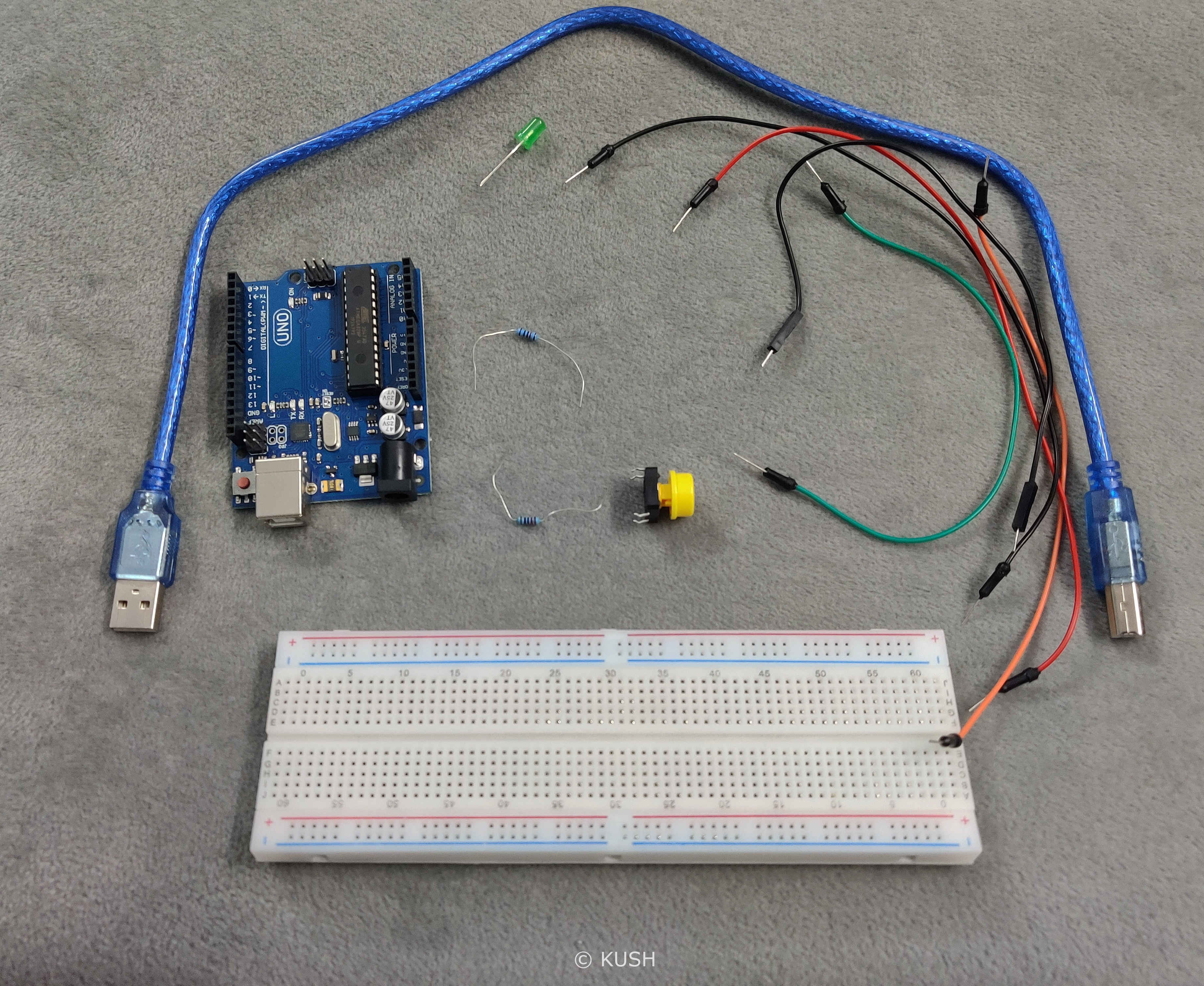
- A Platform for the software End. Laptop, PC etc. with Arduino IDE installed.
- An Arduino board (Arduino UNO R3 suggested). Note: If you don’t have an Arduino, you can use it virtually
- USB cable to power the Arduino
- Five Jumper wires for connection
- Breadboard
- One 10k ohms Resistor for Button and One 220ohms Resistor for LED
- One LED
- One push-button
Got everything? Okay! We’re good to go.
Components Explanation:
Before we start with the assembly of the Hardware, it’s better to understand the use of the components.
Breadboard is a device used for making temporary connections with Arduino. It is used to avoid soldering. Breadboard’s interface is really easy to understand and use. It is divided into three parts. The leftmost and rightmost portions consist of two vertical columns each, with many holes which are connected to each other. That means if we connect one hole of that row to power, the whole vertical row gets connected to power. These holes are labelled as ‘+’ and ‘-‘. Generally the ‘+’ sign row, marked with red is used for providing power to the components and the ‘-‘ sign row, marked with blue is used for grounding the components.
Note: Grounding is connecting the components to Earth in order to prevent overflow of current at the time of accidental cut.
The middle portion consists of horizontal rows with holes in a group of five, which are connected to each other. That means if we connect one hole of that group to certain pin on Arduino, the whole horizontal group of five gets connected to it.
Resistor is used for reducing the current flow by causing resistance to the flow. It is used to prevent our LED from burning in the case of excess current flow.
Push-Button is a device which basically turns something ON or OFF. When the push button is pressed, it’s legs get connected therefore allowing the current to flow. Whereas when it is not pressed, the legs are not connected, hence the circuit is incomplete.
USB wire is used to power the Arduino. We can also use a power adapter but for our project, power supply through USB is enough. Jumper wires are used to connect the components. LED has two legs, one of them is shorter than other. The shorter one is called Cathode (negative) and the longer one is called Anode (positive). The current flows from Anode to Cathode, therefore the orientation of the LED is important. This project can also be performed by increasing the number of LED’s and resistors but we used 3 LED’s for simplicity
What is a Serial Monitor? Serial Monitor is a link or a tie up between your computer and the Arduino Board. We can interact with the Arduino Board using the Serial Monitor. We can send and receive messages through it. It comes really handy while debugging but for this example we will use it for receiving the status of the LED. Serial Monitor can be accessed by going to Arduino IDE > Tools > Serial Monitor. Or you can also use a shortcut command [ctrl + shift + M] for the same.
Hardware Assembly:
Now, let’s start with assembling the Hardware:
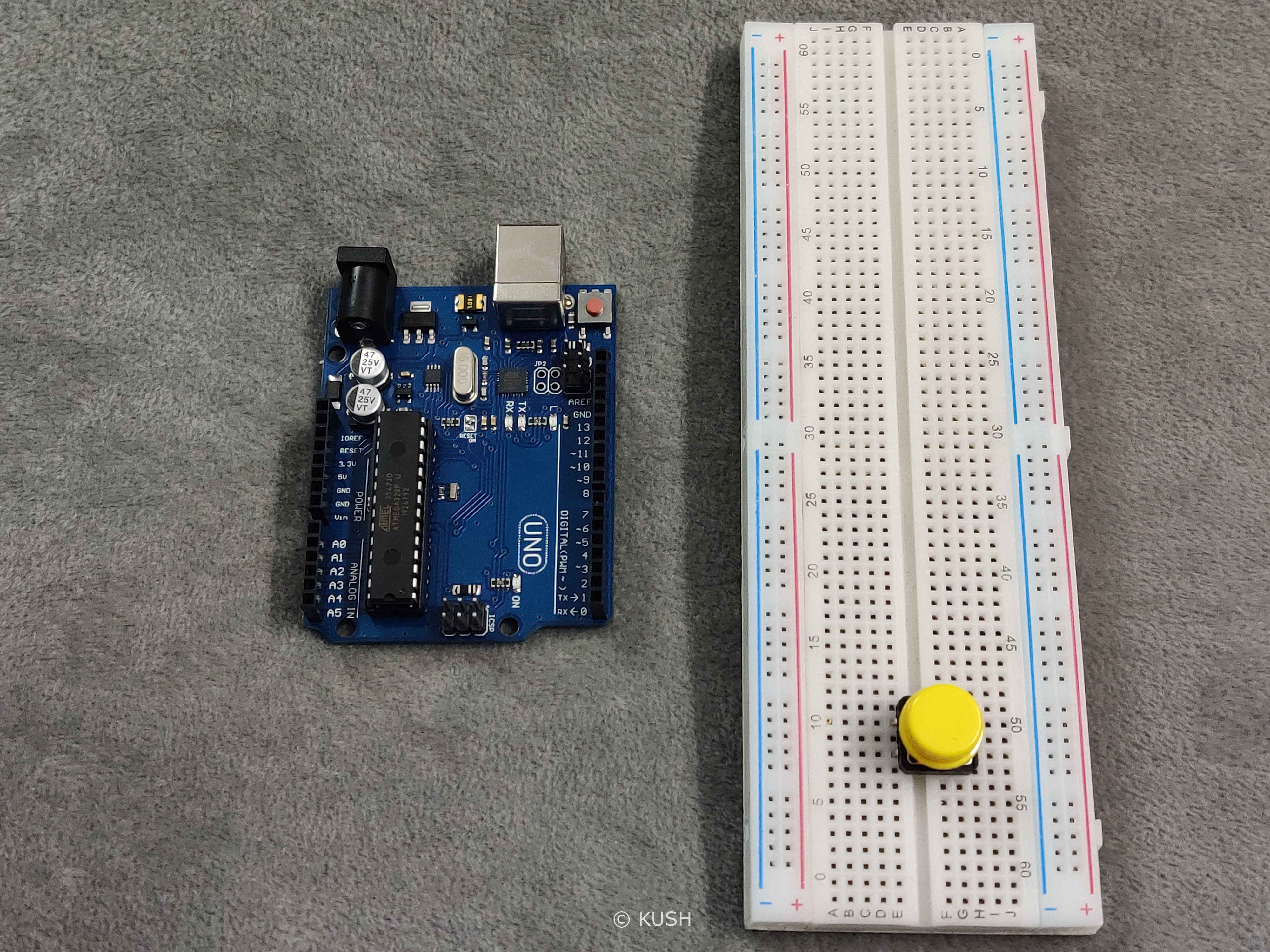
- Firstly take a push-button and connect it across the middle gap of the Breadboard into the holes.
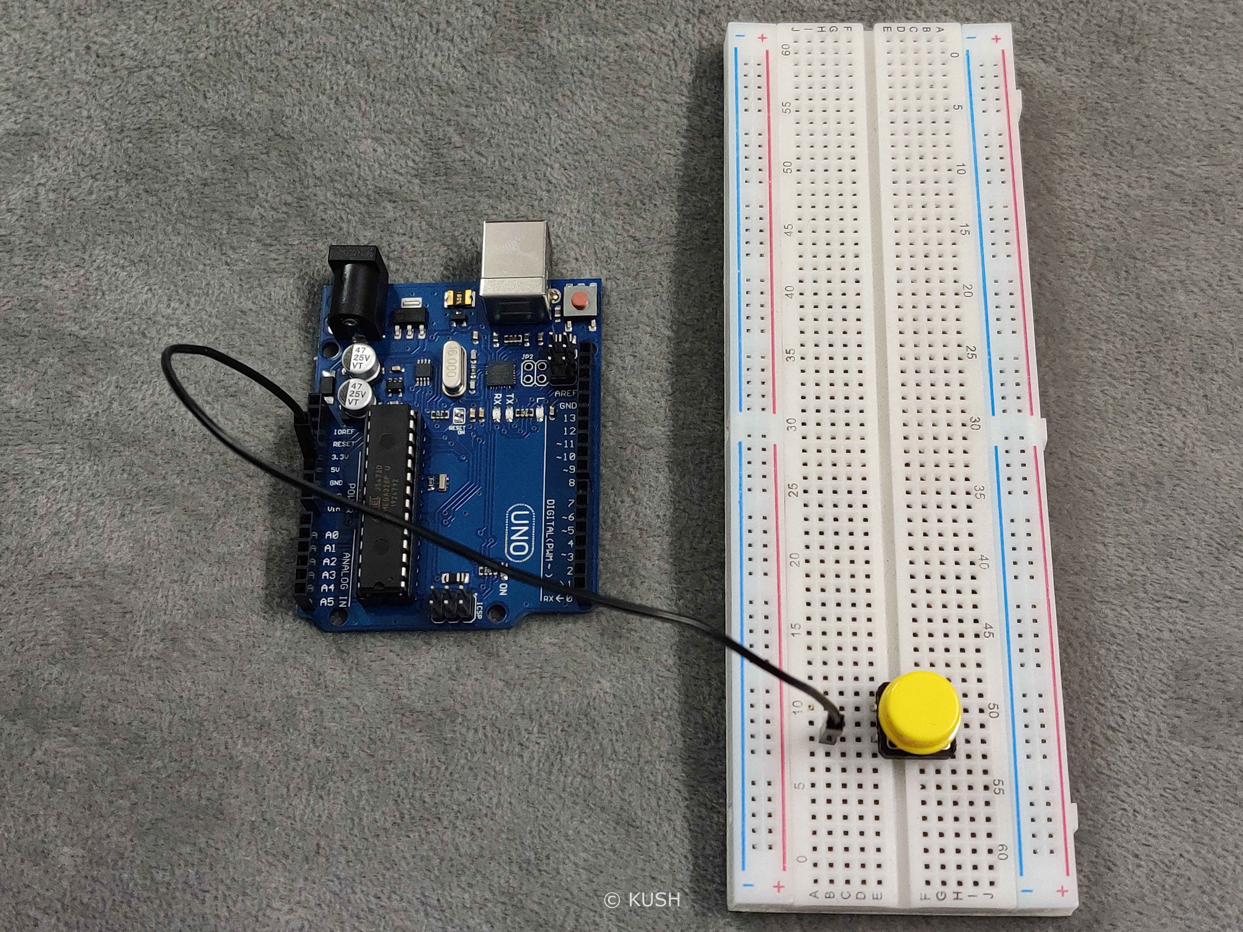
- Now take a jumper wire and connect it’s one end to the 5V power pin on the Arduino and other end to one of the leg of push-button
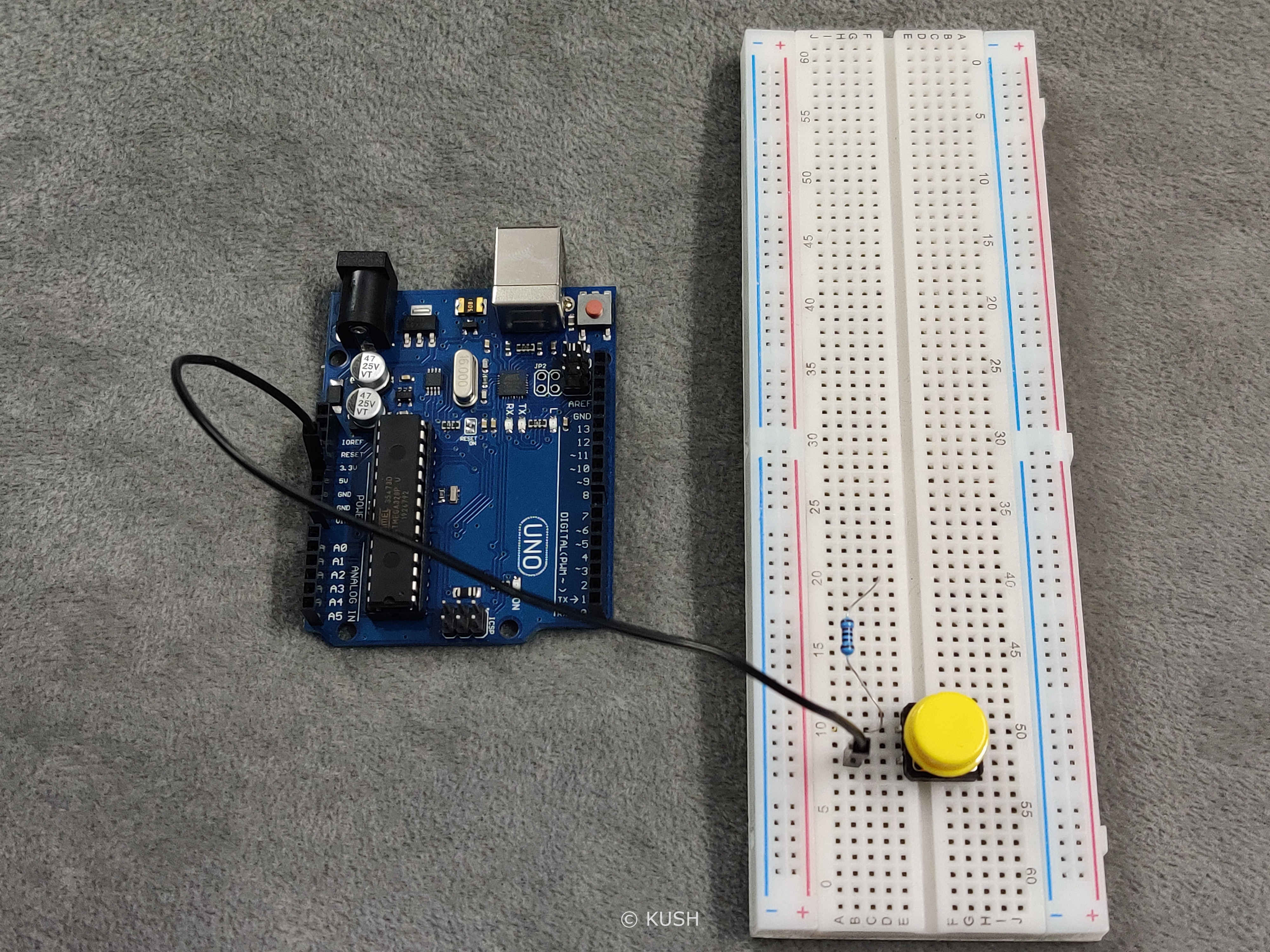
- Take a 10K ohms resistor and insert it’s one leg to the push-button’s that leg to which the ‘power’ jumper wire is not connected. Insert the other leg to any other horizontal group of holes.
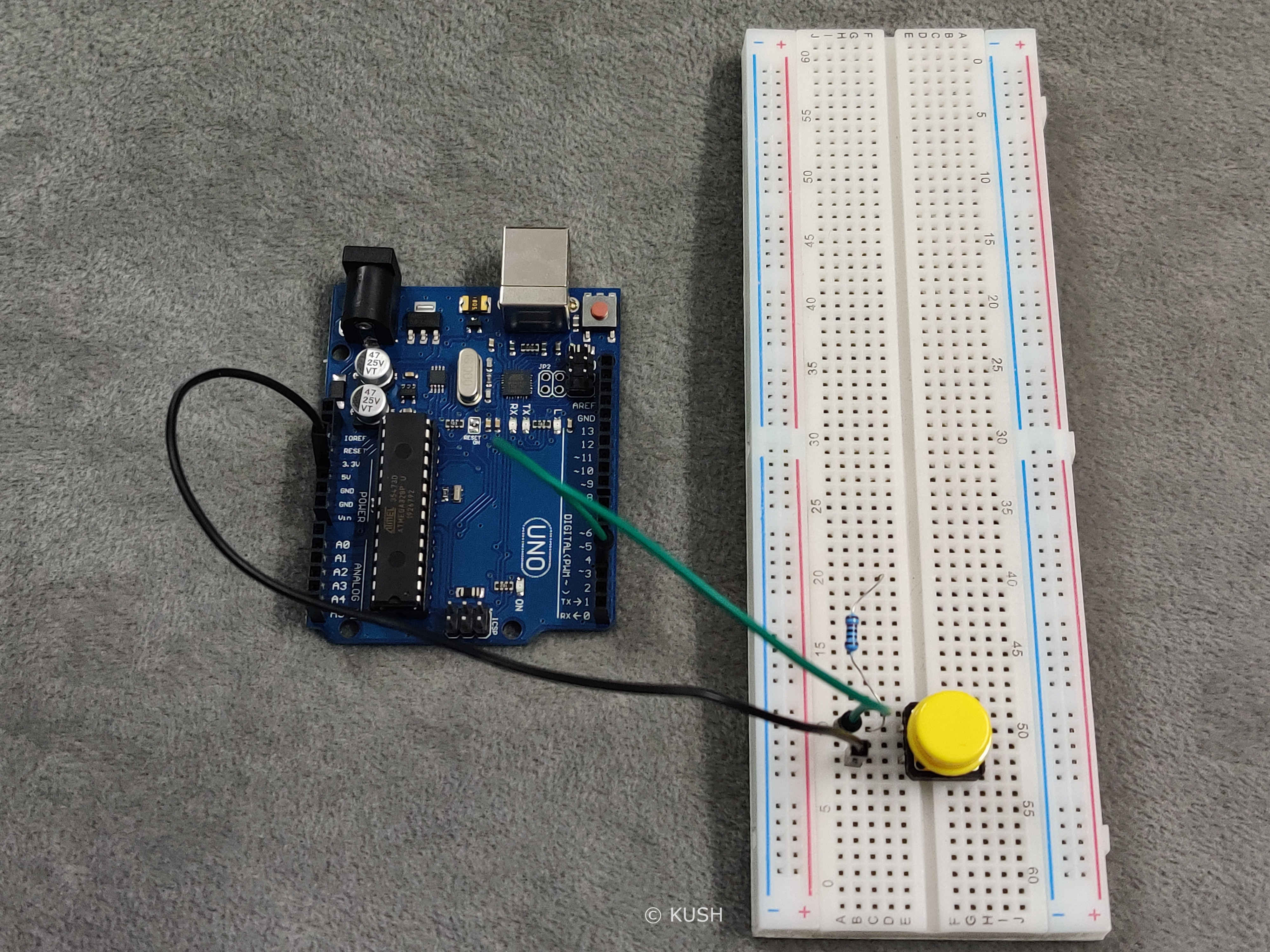
- Now take a Jumper wire and connect it’s one end to pin3 on the Arduino and other end to the group of holes to which the Resistor and push-button is connected.
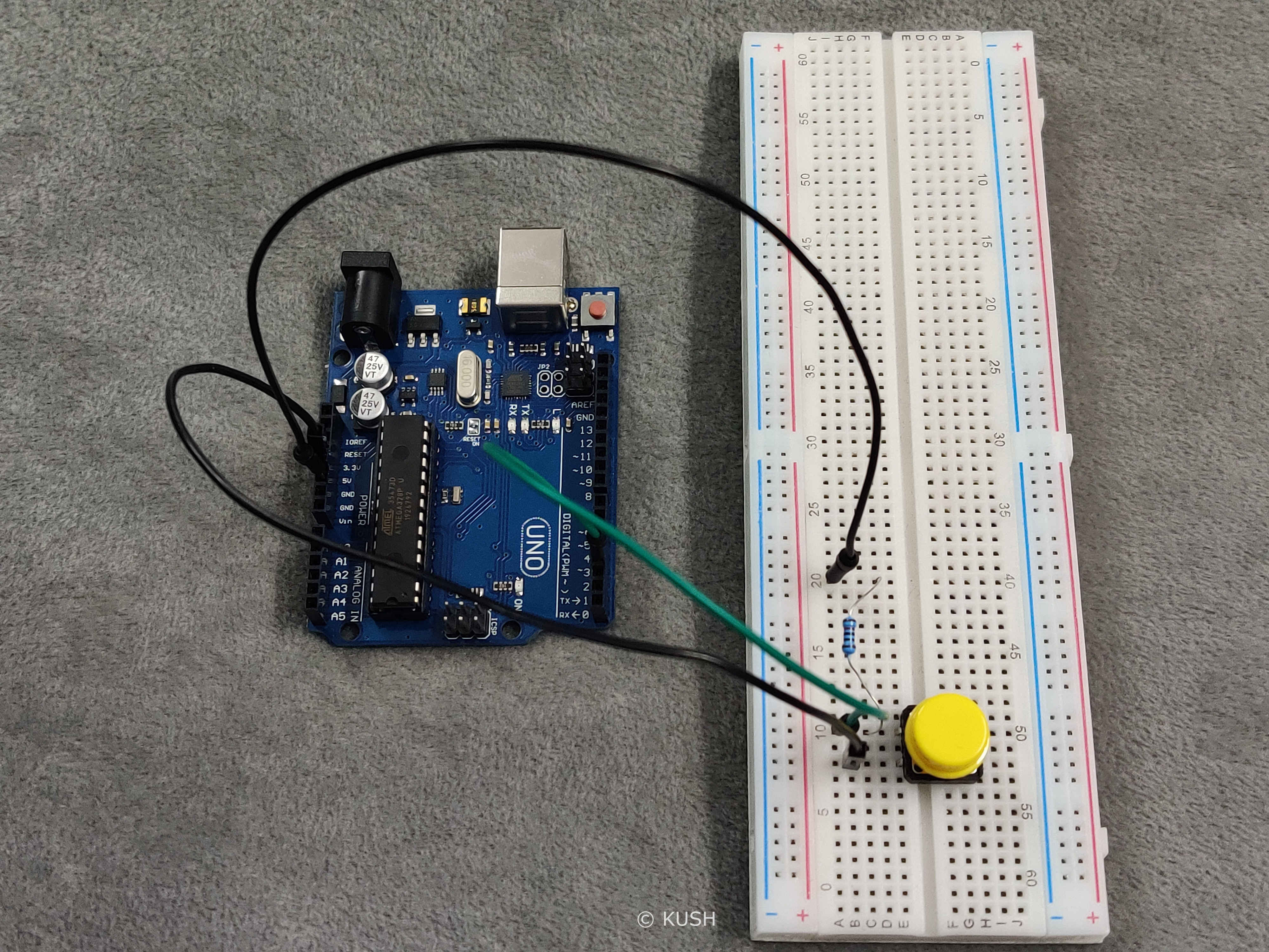
- Take another jumper wire and connect it’s one end to the resistor and other end to the Ground pin on the Arduino.
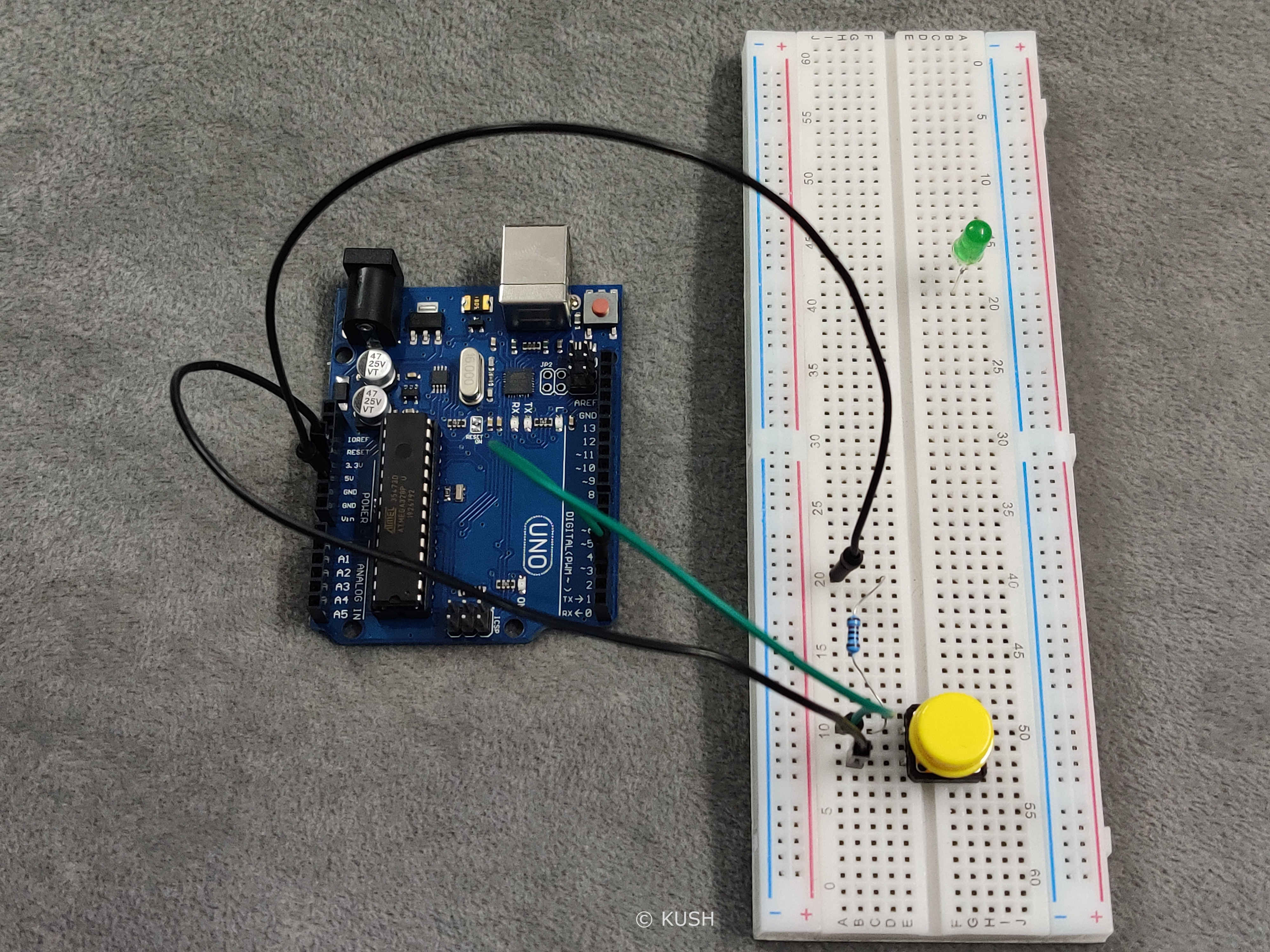
- Now take a LED, connect it to any horizontal group of holes, other than one’s already used.
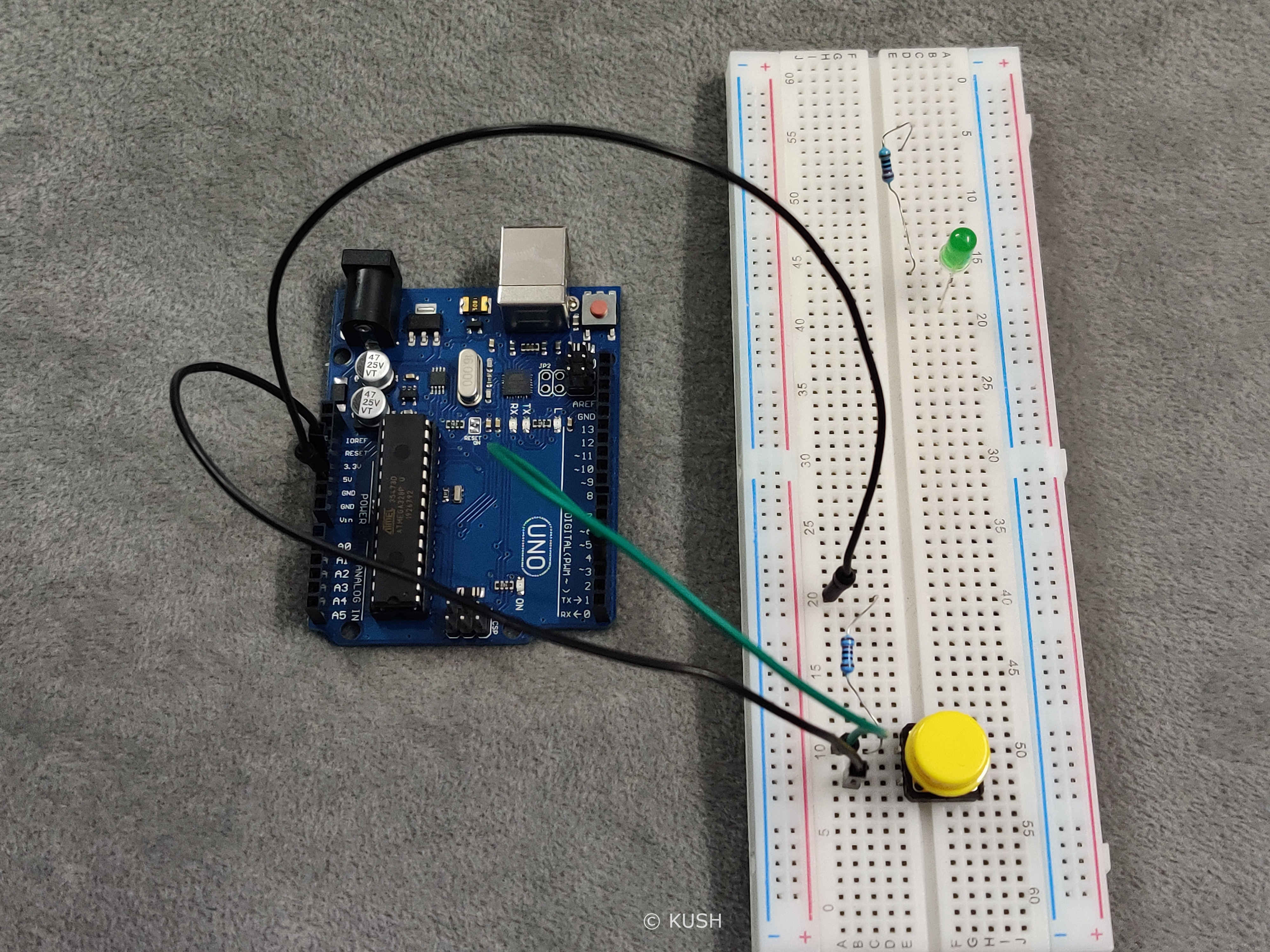
- Now take a 220ohms resistor and connect it’s one leg to the Cathode (shorter) leg of the LED and connect the other leg to any other group of holes.
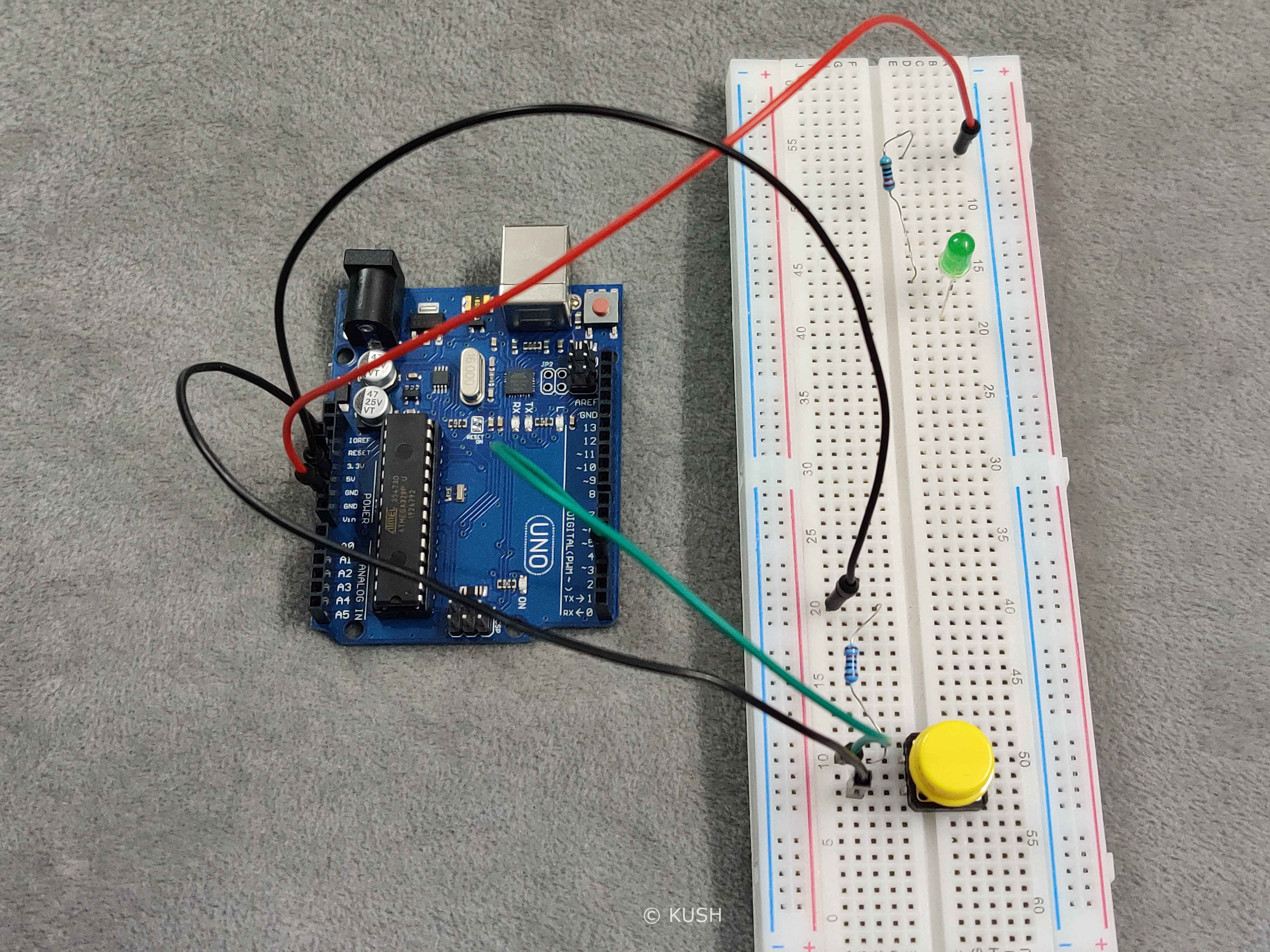
- Take a jumper wire and connect it’s one end to the Ground pin on the Arduino and other end to the Resistor
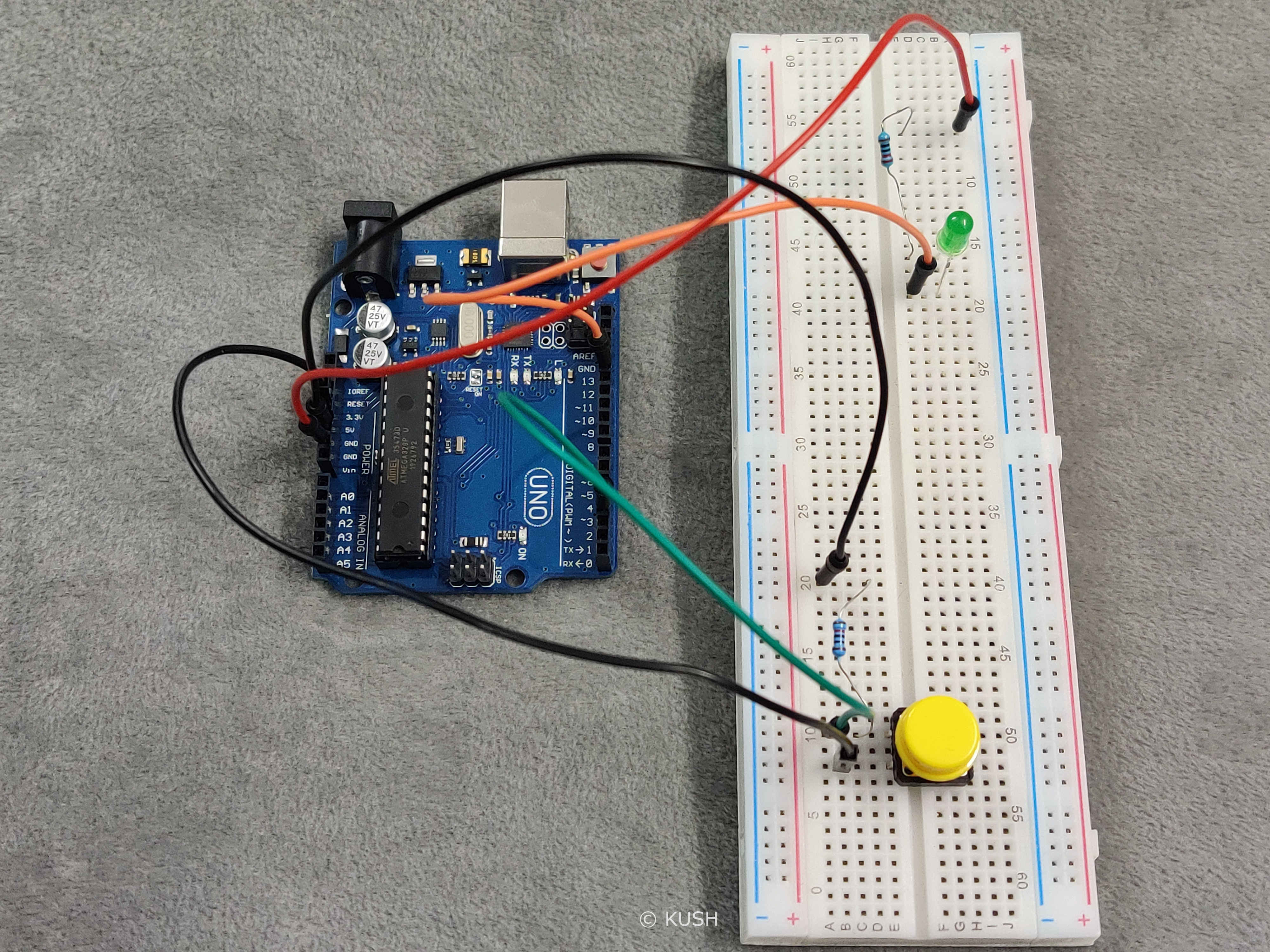
- Lastly, take another jumper and connect it’s one end to the Pin13 on the Arduino and other end to the Anode(longer) leg of the LED.
Hardware Explanation:
In the case of push-button, Jumper wire that is connected to the Pin3 on the Arduino and the resistor are in the same group of holes, therefore they get connected. And as the resistor is grounded, therefore any extra value is pulled to ground which avoids floating of input value from Ground to 5V. The push-button is connected to 5V power supply and any input from Push-button is read on the Pin3 on the Arduino.
In the case of LED, it’s cathode leg and resistor are in the common group of holes, therefore they get connected. And as the Resistor is grounded, it avoids any extra current flow and hence avoiding LED from fusing.
As the assembly of hardware is done, now it’s time for writing the program and uploading it to the Arduino.
Note: For programming the Arduino, C/C++ language is used. If you don’t know anything about C, just make sure to pay more attention to it. I’ve explained the code and also added comments within the program for better understanding.
Program:
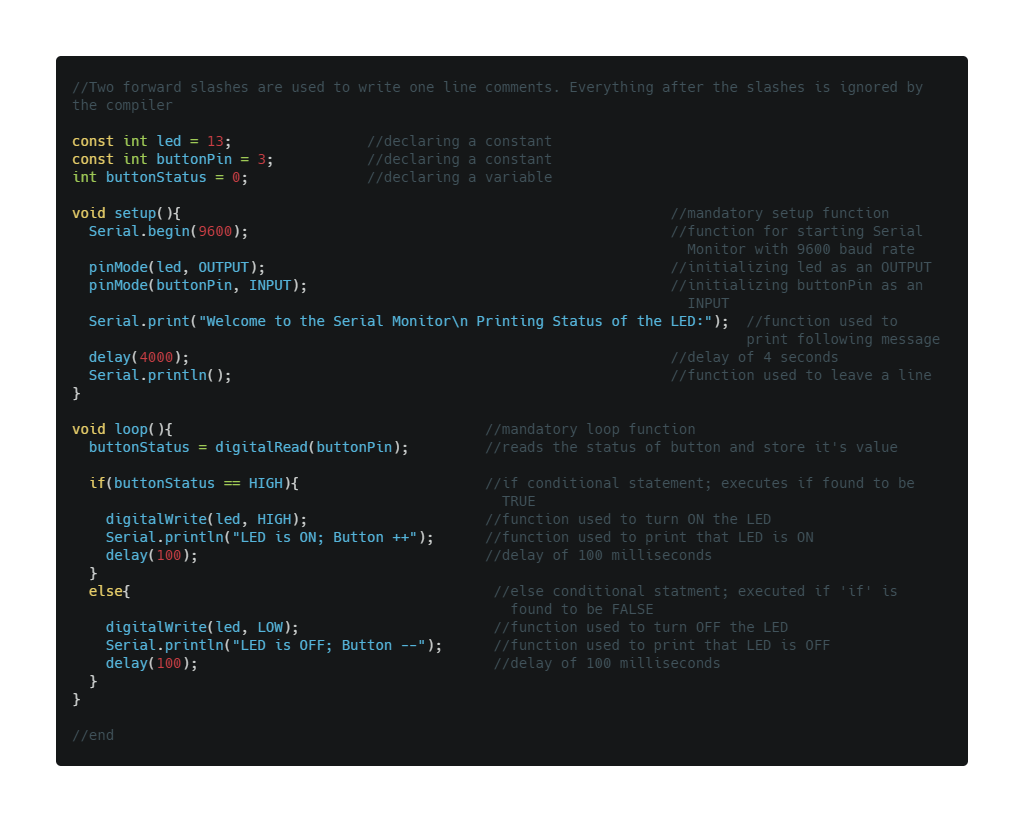
const int led = 13;
const int buttonPin = 3;
int buttonStatus = 0;

void setup(){
  Serial.begin(9600);
  pinMode(led, OUTPUT);
  pinMode(buttonPin, INPUT);
  Serial.print("Welcome to the Serial Monitor\n Printing Status of the LED:");
  delay(4000);
  Serial.println();
}

void loop(){
  buttonStatus = digitalRead(buttonPin);

  if(buttonStatus == HIGH){
    digitalWrite(led, HIGH);
    Serial.println("LED is ON; Button ++");
    delay(100);
  }
  else{
    digitalWrite(led, LOW);
    Serial.println("LED is OFF; Button --");
    delay(100);
  }
}
Program Explanantion:
In C language, the first step is to declare the constant or variables that we are going to use in the program. Here,’const int pin = 13;’ declares that “pin” is an integer with a constant value 13, which is the pin for the LED. ‘const int buttonPin = 3;’ declares that “buttonPin” is an integer with a constant value 3, which is the pin for the button. ‘int buttonStatus = 0;’ declares that “buttonStatus” is an integer with a variable value.
Note: Here i’ve specifically mentioned ‘const’ as buttonStatus is variable
‘buttonStatus’ is just a variable for storing the status of the button i.e. storing the value that whether the button is pressed or not.
Now, in Arduino sketch the “void setup” and “void loop” are the two main functions which are mandatory for every Arduino sketch. The curly brackets ‘{}’ after any statement is used to define a clear scope and is also used to group statements for better understanding. (Note: An open curly bracket must always be closed after grouping the statements)
The ‘Setup’ function is only executed once at the beginning of the program and the ‘loop’ function executes repeatedly. The term ‘void’ here is used to signify that these functions do not return anything and they don’t take any arguments. (Note: Argument is as a value provided to the function whenever we call it. They are passed inside the bracket ‘()’ by the function).
Now the function ‘Serial.begin(9600);’ is used to start the Serial monitor, where 9600 is the Baud Rate i.e. exchanging data at 9600 bits per second. There can be different baud rates but 9600 is the most common baud rate. The function ‘pinMode’ is used to declare an INPUT or OUTPUT. The function ‘pinMode(led, OUTPUT);’ declares OUTPUT at the pin13. The function ‘pinMode(buttonPin, INPUT);’ declares INPUT on pin3. Now the function ‘Serial.print(“Welcome to the Serial Monitor\n Printing Status of the LED:”);’ is used to print something to the Serial Monitor. Anything inside the inverted commas “” gets printed.
Note: ‘\n’ is used to add another line. Therefore anything after \n is printed in the other line.
The function ‘delay(4000);’ is used to hold the above message for 4 seconds and ‘Serial.println();’ is used to leave a line before printing anything else.
Now the function ‘buttonStatus = digitalRead(buttonPin);’ is used to read the status of button on pin3 and store it to the variable ‘buttonStatus’. Now the ‘if’ and ‘else’ are conditional statements. According to which if it returns TRUE, the following statements gets printed and if it returns false, we move on to ‘else’ statement and check it. Therefore, ‘if(buttonStatus == HIGH){‘ basically states that if the value of pin3 stored into buttonStatus is HIGH i.e. TRUE or 1, then execute the following statements mentioned in the curly brackets.
Now the function ‘digitalWrite(led, HIGH);’ makes the LED on pin13, HIGH i.e. Turn ON. And when the LED is ON, ‘Serial.println(“LED is ON; Button ++”);’ prints “LED is ON; Button ++” to the Serial Monitor. Then the ‘delay(100);’ holds the above message for 100 miliseconds before printing another message.
Now if the “if” statement is found to be false, ‘digitalWrite(led, LOW);’ gets executed which basically makes the LED on pin13, LOW i.e. Turn OFF. And ‘ Serial.println(“LED is OFF; Button –”);’ prints “LED is OFF; Button –” to the Serial Monitor. Then the ‘delay(100);’ holds the above message for 100 miliseconds before printing another message.
You might be wondering that what is the use of a semicolon ‘;’ after every piece of code. Well, in C/C++ semicolon acts as a Terminator and it used to tell the compiler that we have reached the end of the command. Semicolon at the end of a command is mandatory in C/C++ language.
Now, we are done with our Program and Hardware. It’s time to upload the sketch to the Arduino.
- Use the USB cable provided with Arduino to connect it with the PC.
- Use ‘Upload’ to verify and upload the sketch to the Arduino.
Note: If you get any errors while compiling the sketch, just make sure the Arduino is connected correctly to the PC and the ‘board’ & ‘port’ is specified in the tools menu. Also check for any errors in the code itself, especially look for unclosed curly brackets or missing semicolons at the end of the statements.
Once the program is successfully verified and uploaded to the Arduino we will see a ‘Done Uploading’ message at the bottom of the screen and the LED will start blinking everytime the button is pushed
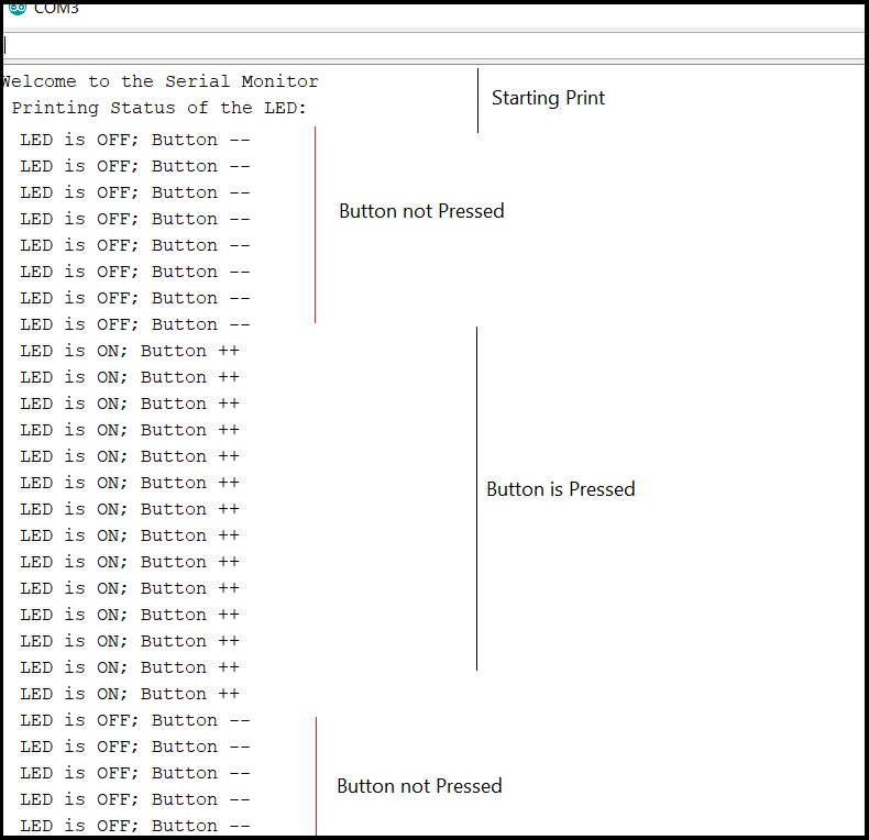
And if we open the Serial Monitor we will see that the status of the button and the LED are being printed, as shown above.
Conclusion:
In this blog we learnt how to use push-button with an LED and we also learnt how to use the Serial Monitor. This was just a basic Example; We will keep stepping up. So for many more such projects, stay tuned!
Thank You!
Share on: