Sequential LED
Arduino Projects ·Introduction
Hey Guys! I hope all of you are doing really great! Today i’ll be showing you how to make differnt LED’s follow a sequential order.
Note: If you are new to IOT and don’t know anything about programming or Hardware, these Blogs are for you as i’ll be starting from very basic and will be explaining everything. So all you need is an urge to learn!
Modules Used:
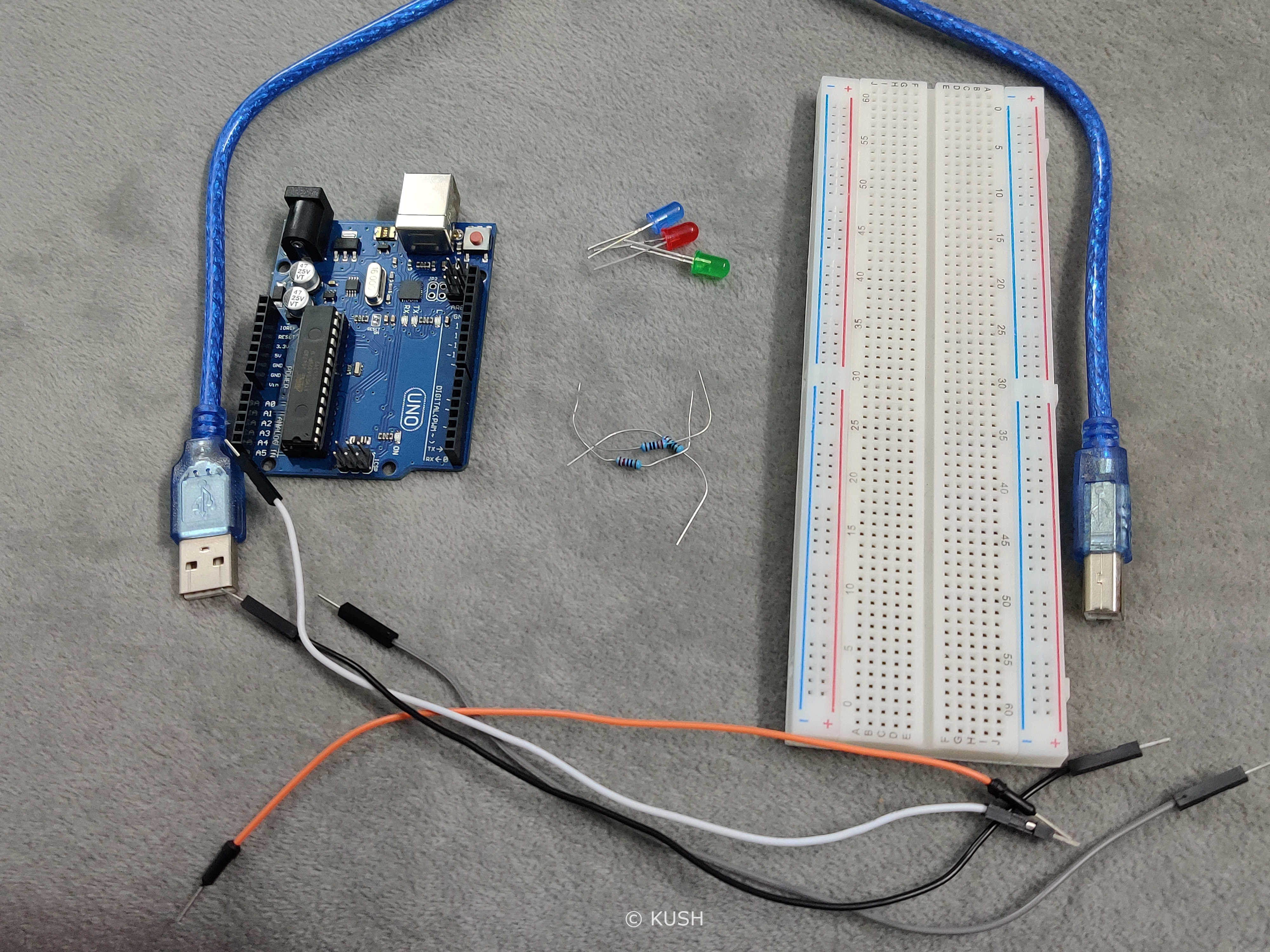
- A Platform for the software End. Laptop, PC etc. with Arduino IDEinstalled.
- An Arduino Board (Arduino UNO R3 suggested). Note: If you don’t have an Arduino, you can use it virtually
- USB cable to power the Arduino
- Four Jumper wires for connection
- Breadboard
- Three Resistors (220 ohms)
- Three LED
Got everything? Okay! We’re good to go.
Components Explanation:
Before we start with the assembly of the Hardware, it’s better to understand the use of the components.
Breadboard is a device used for making temporary connections with Arduino. It is used to avoid soldering. Breadboard’s interface is really easy to understand and use. It is divided into three parts. The leftmost and rightmost portions consist of two vertical columns each, with many holes which are connected to each other. That means if we connect one hole of that row to power, the whole vertical row gets connected to power. These holes are labelled as + and -. Generally the + sign row, marked with red is used for providing power to the components and the - sign row, marked with blue is used for grounding the components.
Note: Grounding is connecting the components to Earth in order to prevent overflow of current at the time of accidental cut.
The middle portion consists of horizontal rows with holes in a group of five, which are connected to each other. That means if we connect one hole of that group to certain pin on Arduino, the whole horizontal group of five gets connected to it.
Resistor is used for reducing the current flow by causing resistance to the flow. It is used to prevent our LED from burning in the case of excess current flow.
USB wire is used to power the Arduino. We can also use a power adapter but for our project, power supply through USB is enough. Jumper wires are used to connect the components. LED has two legs, one of them is shorter than other. The shorter one is called Cathode (negative) and the longer one is called Anode (positive). The current flows from Anode to Cathode, therefore the orientation of the LED is important. This project can also be performed by increasing the number of LED’s and resistors but we used 3 LED’s for simplicity
Hardware Assembly:
Now, let’s start with assembling the Hardware:
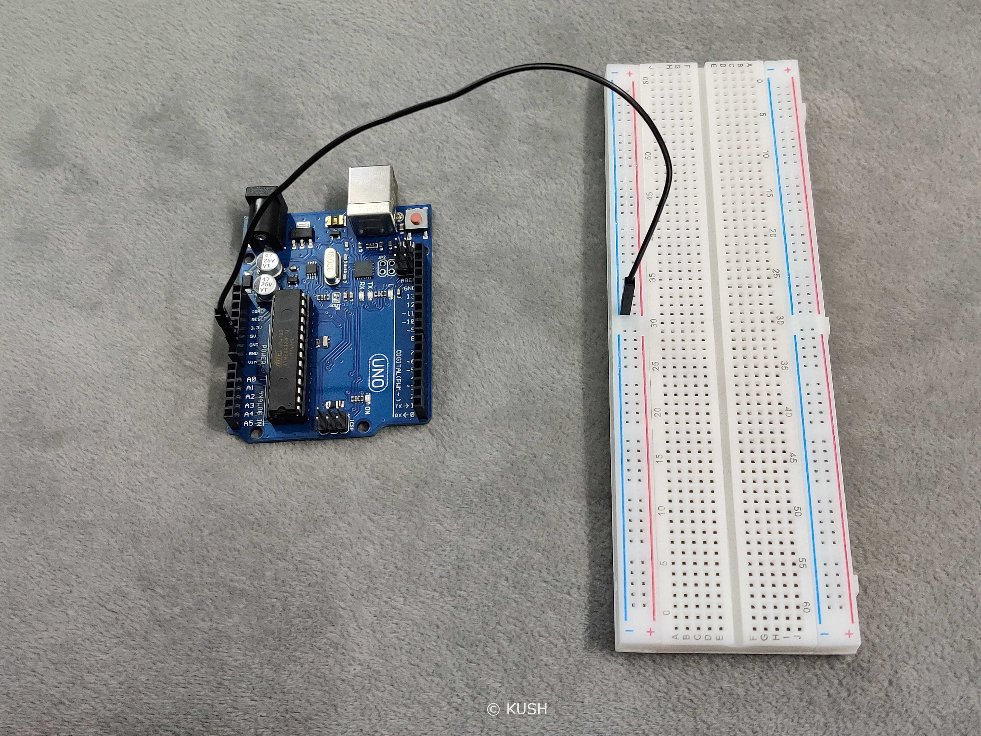
- Firstly take a jumper wire and connect it’s one end to the ground pin on the Arduino and connect the other end to any hole of vertical row labelled as ‘-‘
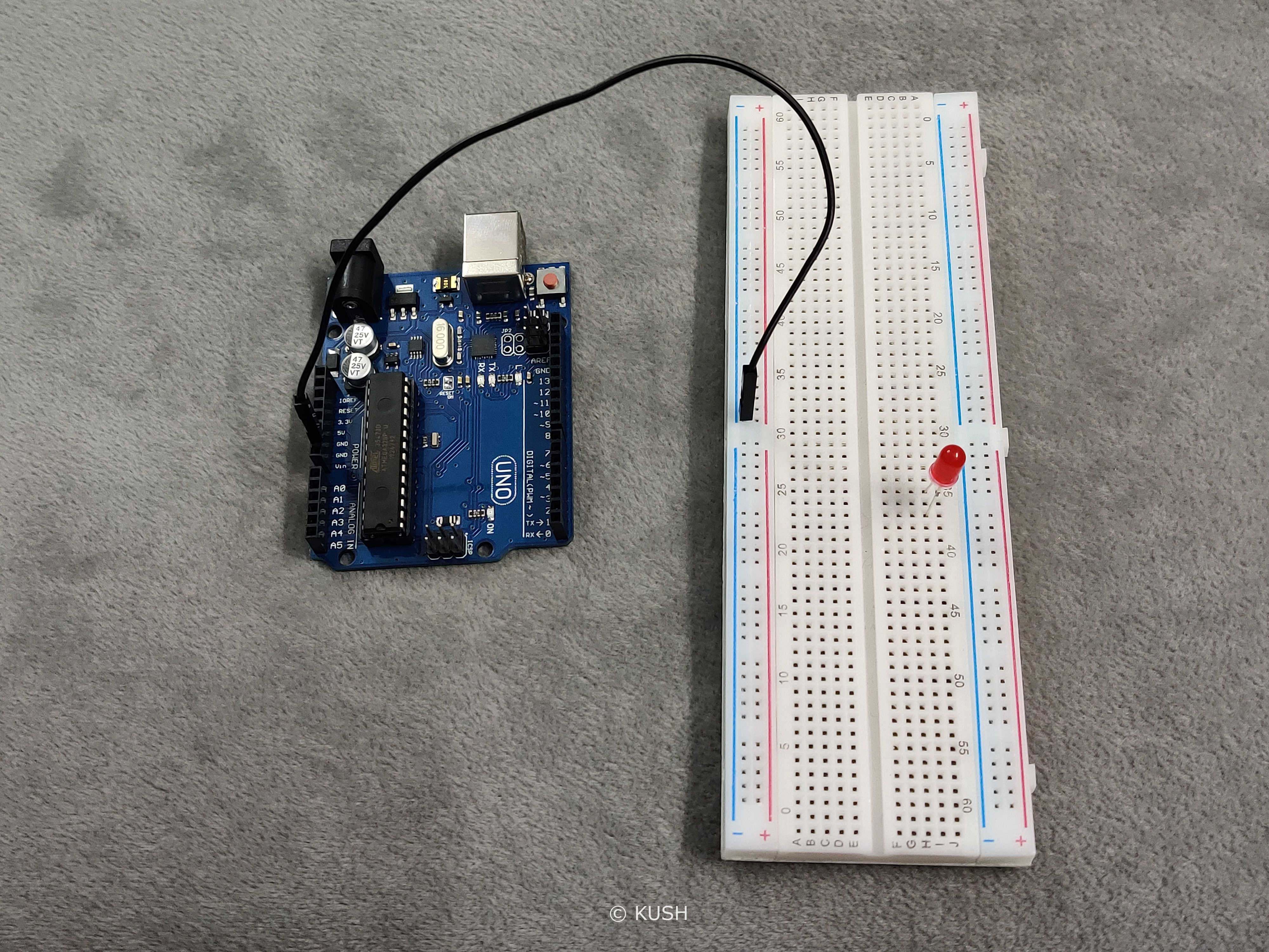
- Now take the LED and insert the longer leg (Anode) into any horizontal hole and insert the other leg (Cathode) to any other horizontal group of holes
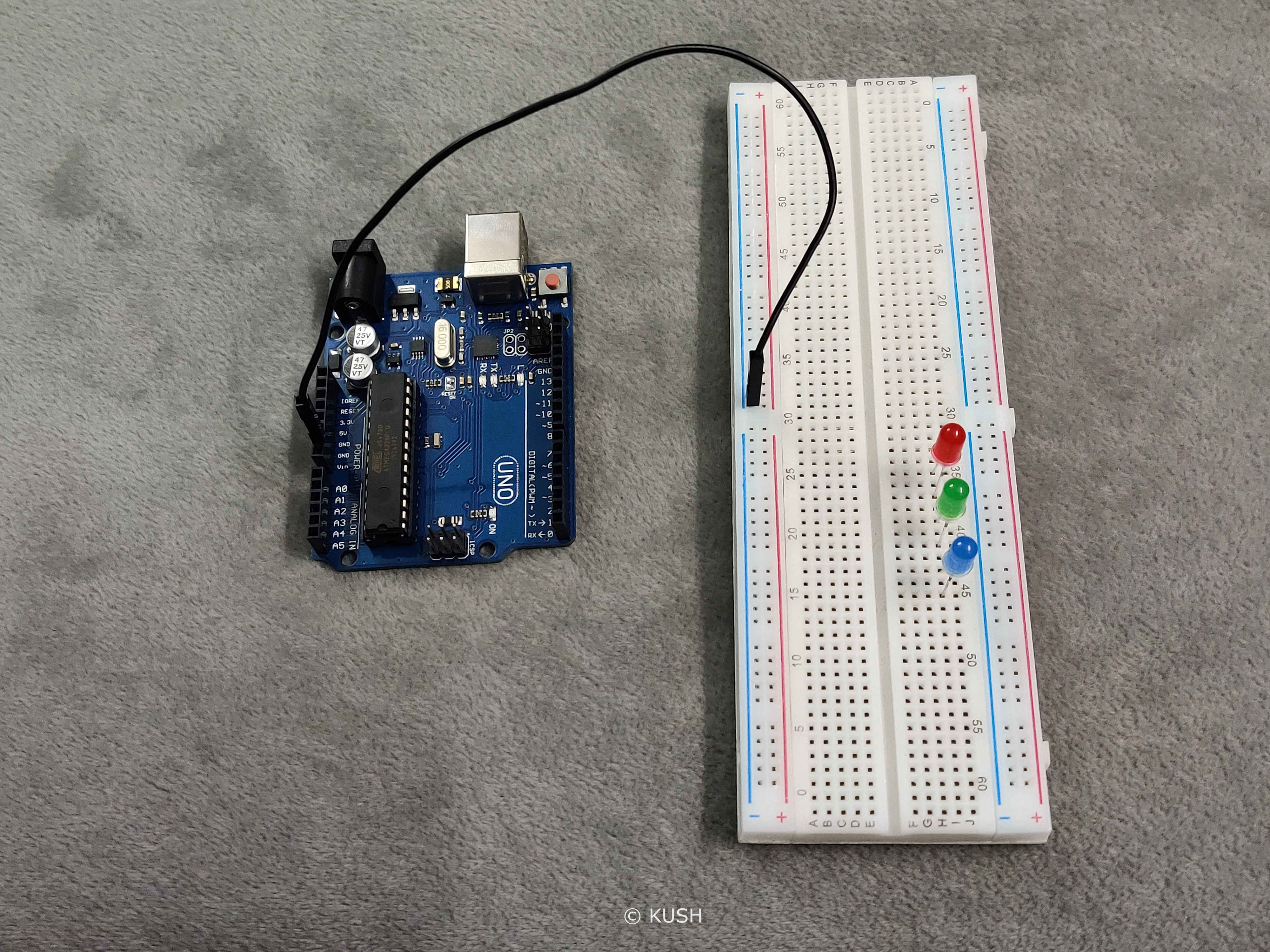
- Repeat the above step with other LED’s (Note: Every LED should be connected to a different horizontal group of holes)
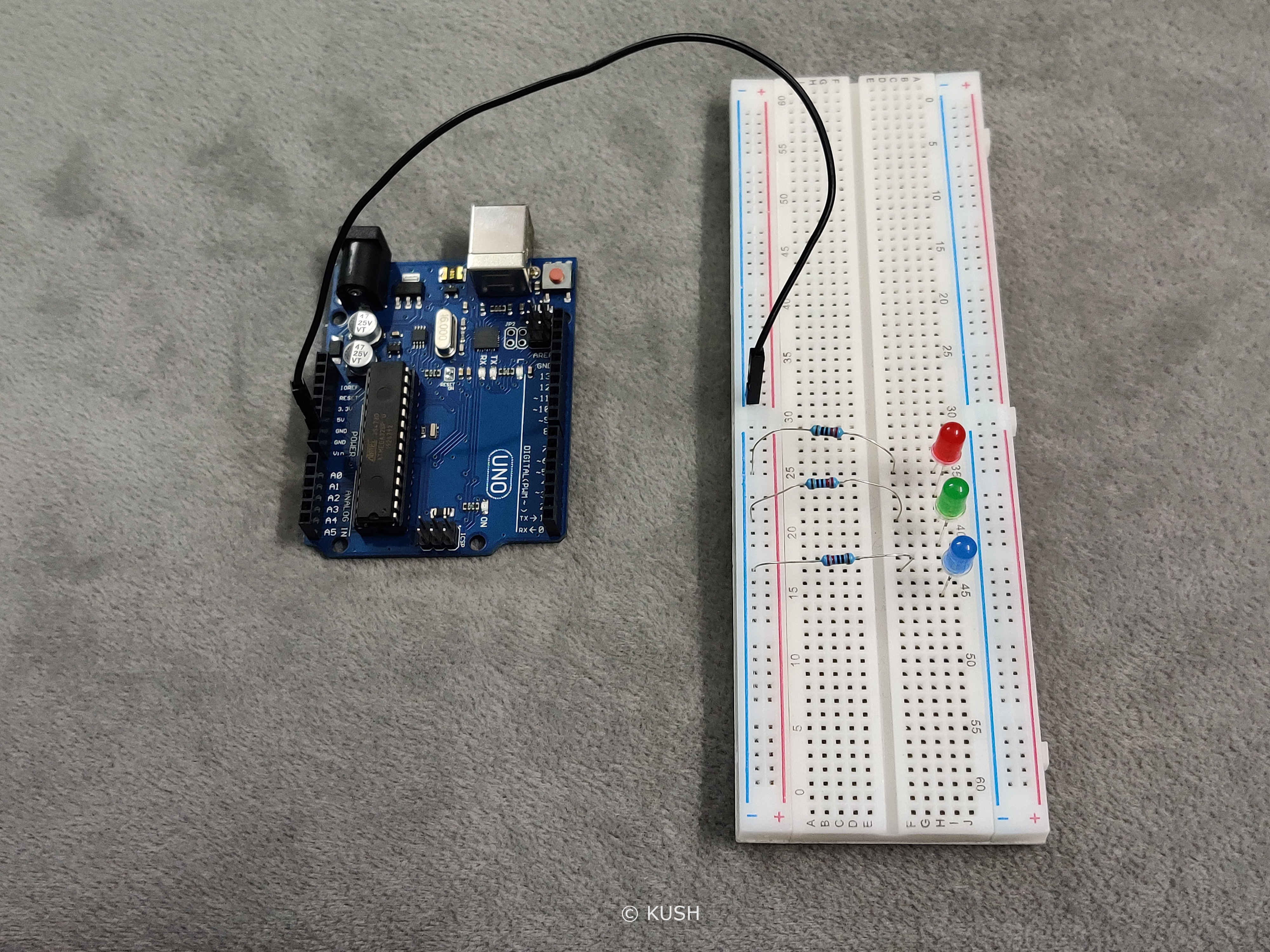
- Now take the resistors. Connect their one end to the vertical row to which the jumper wire is connected and connect the other end to the Cathode (shorter) leg of LED’s.
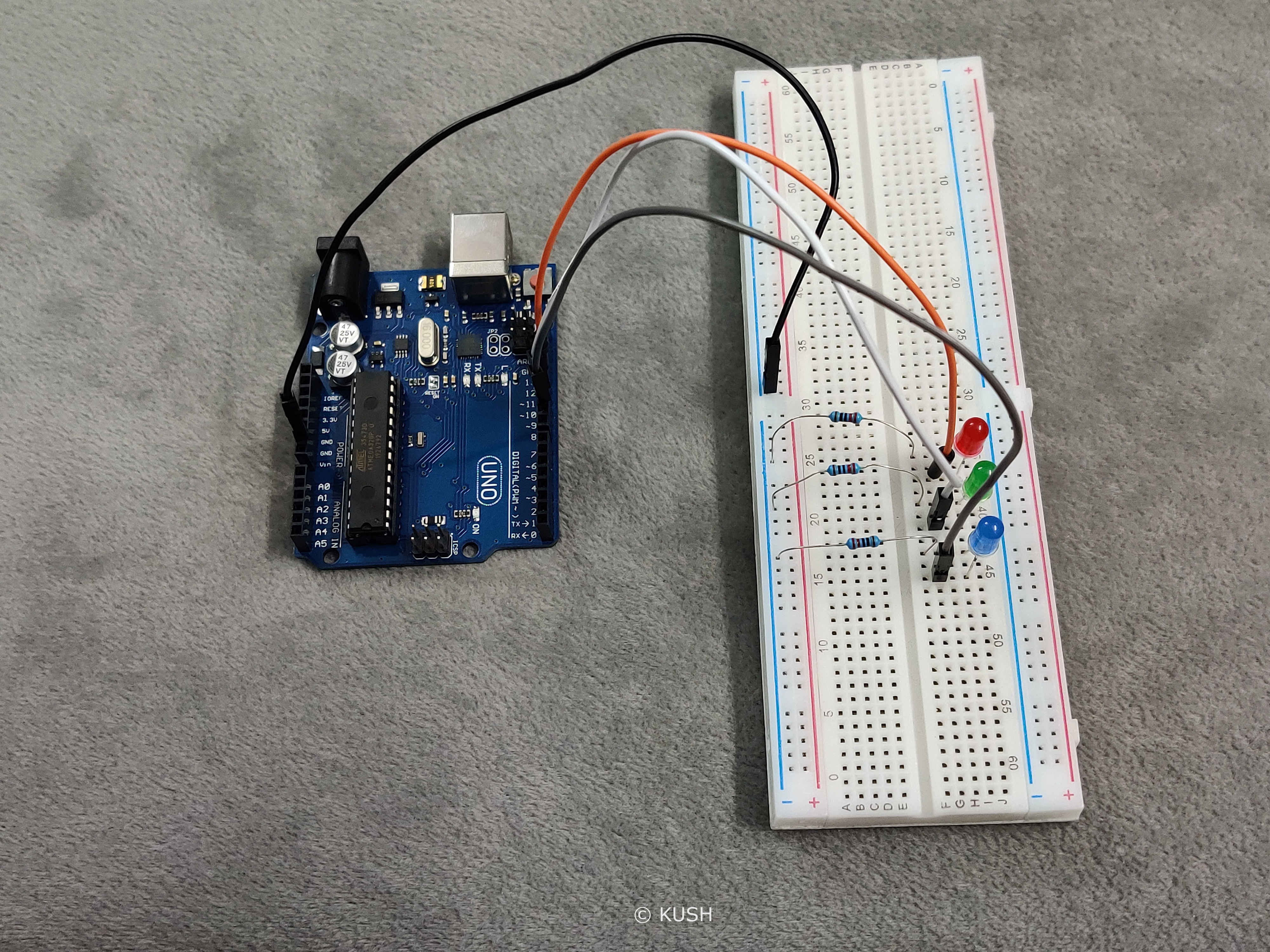
- Now take the jumper wires. Connect their one end to the digital pin12,11 & 10 respectively on the Arduino and other end to the Anode (longer) leg of the LED’s.
Hardware Explanation:
As Jumper wire connected to ground pin on the Arduino and the resistors are in the same group of holes on the vertical row, so they all will get connected to the ground. The other end of the resistors are connected to the Cathode leg of the LED’s, therefore it will avoid fusing of LED’s in the case of excess current Now as the anode leg of the LED’s are connected to Pin12,11 & 10, therefore any action performed on these pins will get displayed on the LED’s.
As the assembly of hardware is done, now it’s time for writing the program and uploading it to the Arduino.
Note: For programming the Arduino, C/C++ language is used. If you don’t know anything about C, just make sure to pay more attention to it. I’ve explained the code and also added comments within the program for better understanding.
Program:
Now there are two ways to write the program for Sequential LED. The first way is to write functions manually for different pins, which is a lengthy method and not something you should use in the long run. Therefore, we will use the second option which is using for loop. It is more appropriate and it saves time.
int pin;
void setup()
{
  pinMode(12, OUTPUT);
  pinMode(11, OUTPUT);
  pinMode(10, OUTPUT);
}

void loop()
{
  for(pin=10; pin<13; pin++){
    digitalWrite(pin, HIGH);
    delay(100);
    digitalWrite(pin, LOW);
    delay(100);
  }
}
Program Explanantion:
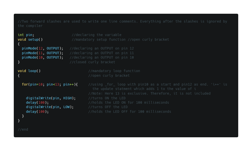
In C language, the first step is to declare the constant or variables that we are going to use in the program. Here, by using ‘int pin;’ we declare that “pin” is an integer.
Now, in Arduino sketch the “void setup” and “void loop” are the two main functions which are mandatory for every Arduino sketch. The ‘Setup’ function is only executed once at the beginning of the program and the ‘loop’ function executes repeatedly. The term ‘void’ here is used to signify that these functions do not return anything and they don’t take any arguments (Note: Argument is as a value provided to the function whenever we call it. They are passed inside the bracket ‘()’ by the function).
The function ‘pinMode’ is used to declare an INPUT or OUTPUT, which in our case is OUTPUT at the digital pins 12,11,10.
Now in order to make the LED follow a sequential order, we will use a for loop which basically execute every statement written inside it. The for loop takes three parameters:
- First is the initialization statement which basically initializes from where to start the loop. It is executed once at the beginning. This parameter is optional.
- Second is the Test expression which is used to test if the desired condition has been met or not. If it returns ‘true’, then the loop is executed again and if it returns ‘false’, then the loop is terminated. It can also be called as an End expression.
- Third is the update statement which basically updates the condition everytime the loop is executed. The above process is repeated until it returns false.
‘i++’ means adding 1 to the value of ‘pin’, everytime the loop is executed. Now the loop ‘for(pin=10; pin<13; pin++)’ basically tells the compiler that initially the value of ‘pin’ is 10. Increase the value of ‘pin’ by 1, till it reaches 12 (where 13 is exclusive) and execute the following code given in the curly brackets, everytime the loop is executed. And once it reaches 12, terminate the loop.
Now in the curly brackets is the code to be executed. So the statement ‘digitalWrite(pin, HIGH);’ makes the specified ‘pin’ HIGH i.e. Turn ON and the statment ‘digitalWrite(pin, LOW);’ makes the specified ‘pin’ LOW i.e. Turn OFF. The ‘delay’ function is used to hold the LED in that state for the mentioned time in milliseconds. Therefore, first the pin10 turns ON, stays ON for 100 milliseconds and then turns OFF, stays OFF for 100 milliseconds. The same process is repeated for pin11 and 12. Once it reaches pin12, the loop is terminated and it goes back to pin10. And this is whole process keeps on executing in a loop.
The curly brackets ‘{}’ after any statment is used to define a clear scope and is also used to group statements for better understanding. (Note: an open curly bracket must always be closed after grouping the statements).
You might be wondering that what is the use of a semicolon ‘;’ after every piece of code. Well, in C/C++ semicolon acts as a Terminator and it used to tell the compiler that we have reached the end of the command. Semicolon at the end of a command is mandatory in C/C++ language.
Now, as we are done with our Program and Hardware. It’s time to upload the sketch to the Arduino.
- Use the USB cable provided with Arduino to connect it with the PC.
- Use ‘Upload’ to verify and upload the sketch to the Arduino.
Note: If you get any errors while compiling the sketch, just make sure the Arduino is connected correctly to the PC and the ‘board’ & ‘port’ is specified in the tools menu. Also check for any errors in the code itself, especially look for unclosed curly brackets or missing semicolons at the end of the statements.
Once the program is successfully verified and uploaded to the Arduino we will see a ‘Done Uploading’ message at the bottom of the screen and the LED’s connected to the Arduino starts blinking in a pattern
Conclusion:
In this blog we learnt what is for loop and how to use it. We also learnt how to make the LED’s glow in a sequential pattern. This was just a basic Example; We will keep stepping up. So for many more such projects, stay tuned!
Thank You!
Share on: