Blinking LED
Arduino Projects ·Introduction
Hey Guys! I hope all of you are doing really great! Today i’ll be showing you how to Blink the built-in and an external LED connected to the arduino and change it’s blinking pattern easily.
Note: If you are new to IOT and don’t know anything about programming or Hardware, these Blogs are for you as i’ll be starting from very basic and will be explaining everything. So all you need is an urge to learn!
Modules Used:
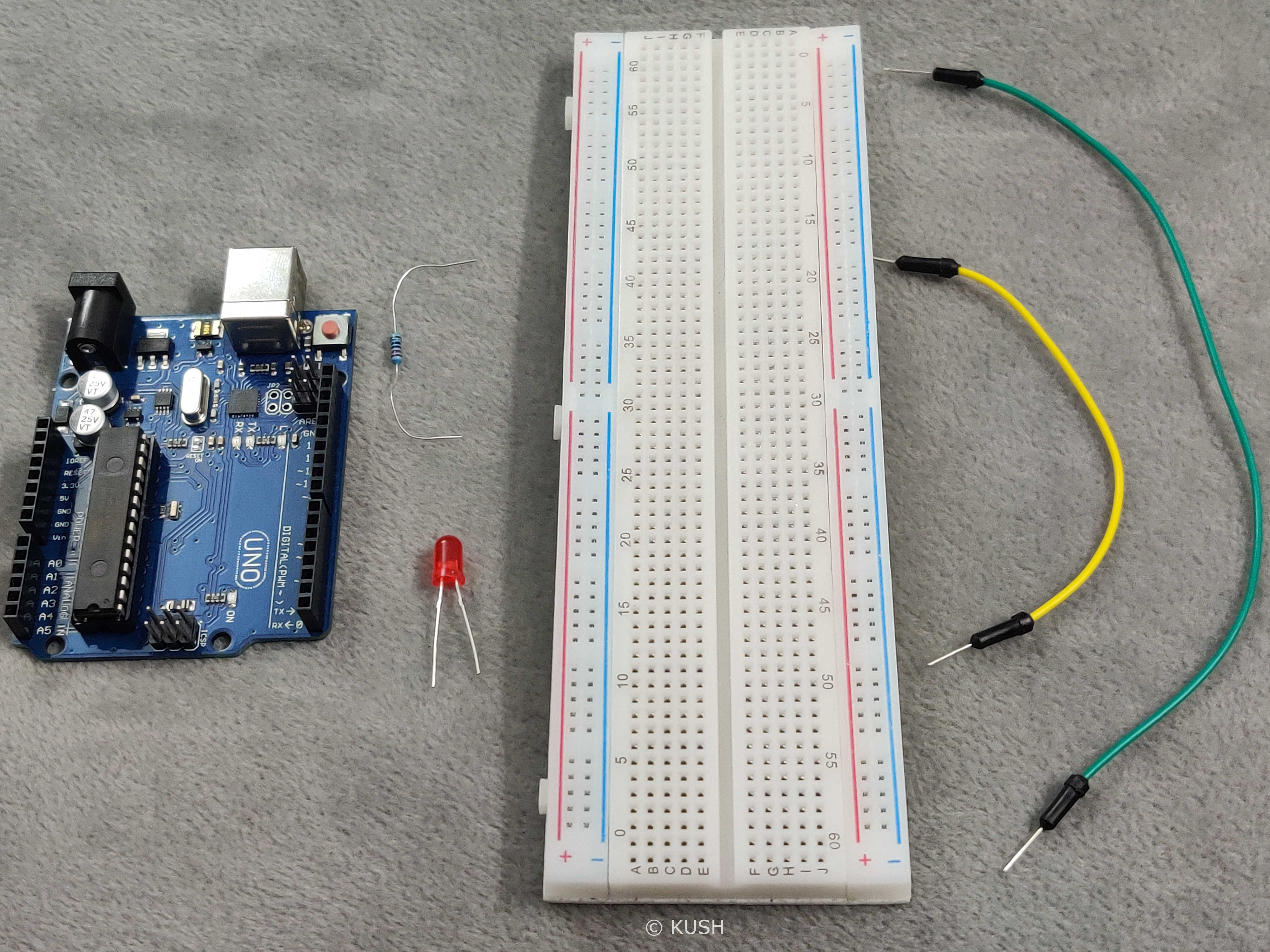
- A Platform for the software End. Laptop, PC etc. with Arduino IDE installed.
- An Arduino Board (Arduino UNO R3 suggested). Note: If you don’t have an Arduino, you can use it virtually
- USB cable to power the Arduino
- Two Jumper wires for connection
- Breadboard
- One Resistor (220 ohms)
- One LED
Got everything? Okay! We’re good to go. While we write code, we also think about the design of the Hardware and it’s Function. But for the sake of simplicity we will first Assemble the Hardware and then we will look at the program.
Components Explanation:
Before we start with the assembly of the Hardware, it’s better to understand the use of the components.
Breadboard is a device used for making temporary connections with Arduino. It is used to avoid soldering. Breadboard’s interface is really easy to understand and use. It is divided into three parts. The leftmost and rightmost portions consist of two vertical columns each, with many holes which are connected to each other. That means if we connect one hole of that row to power, the whole vertical row gets connected to power. These holes are labelled as + and -. Generally the + sign row, marked with red is used for providing power to the components and the - sign row, marked with blue is used for grounding the components.
Note: Grounding is connecting the components to Earth in order to prevent overflow of current at the time of accidental cut.
The middle portion consists of horizontal rows with holes in a group of five, which are connected to each other. That means if we connect one hole of that group to certain pin on Arduino, the whole horizontal group of five gets connected to it.
Resistor is used for reducing the current flow by causing resistance to the flow. It is used to prevent our LED from burning in the case of excess current flow.
USB wire is used to power the Arduino. We can also use a power adapter but for our project, power supply through USB is enough. Jumper wires are used to connect the components. This project can also be performed using the built-in LED on the Arduino but an external LED is preferred for a more visible output and for the sake of numerous applications. LED has two legs, one of them is shorter than other. The shorter one is called Cathode (negative) and the longer one is called Anode (positive). The current flows from Anode to Cathode, therefore the orientation of the LED is important.
Hardware Assembly:
Now, let’s start with assembling the Hardware:
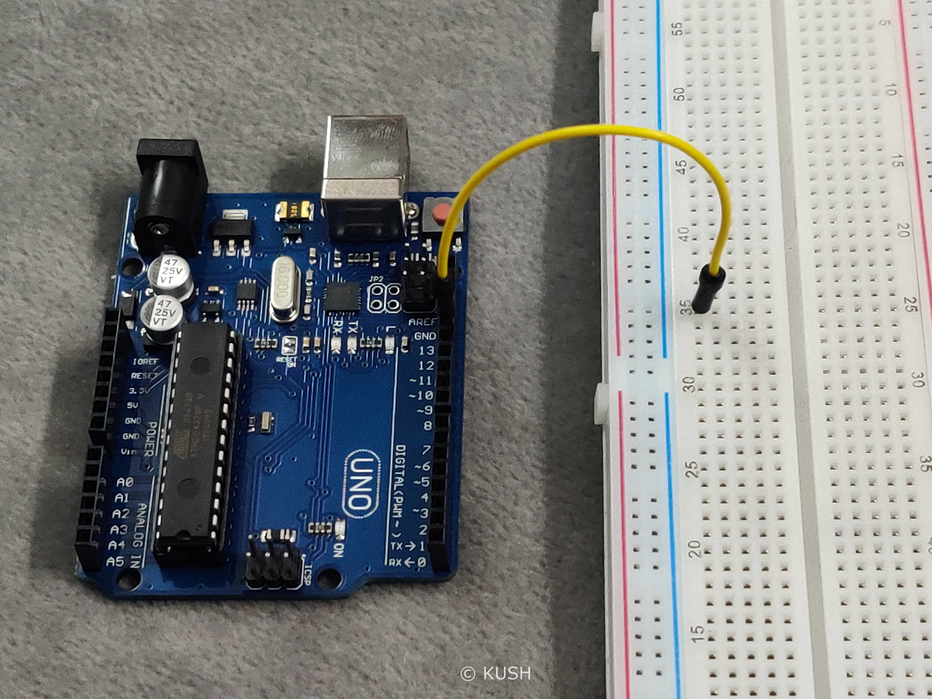
- First connect one Jumper wire to the digital pin13 on the Arduino and connect the other end of the jumper wire to one of the horizontal holes.
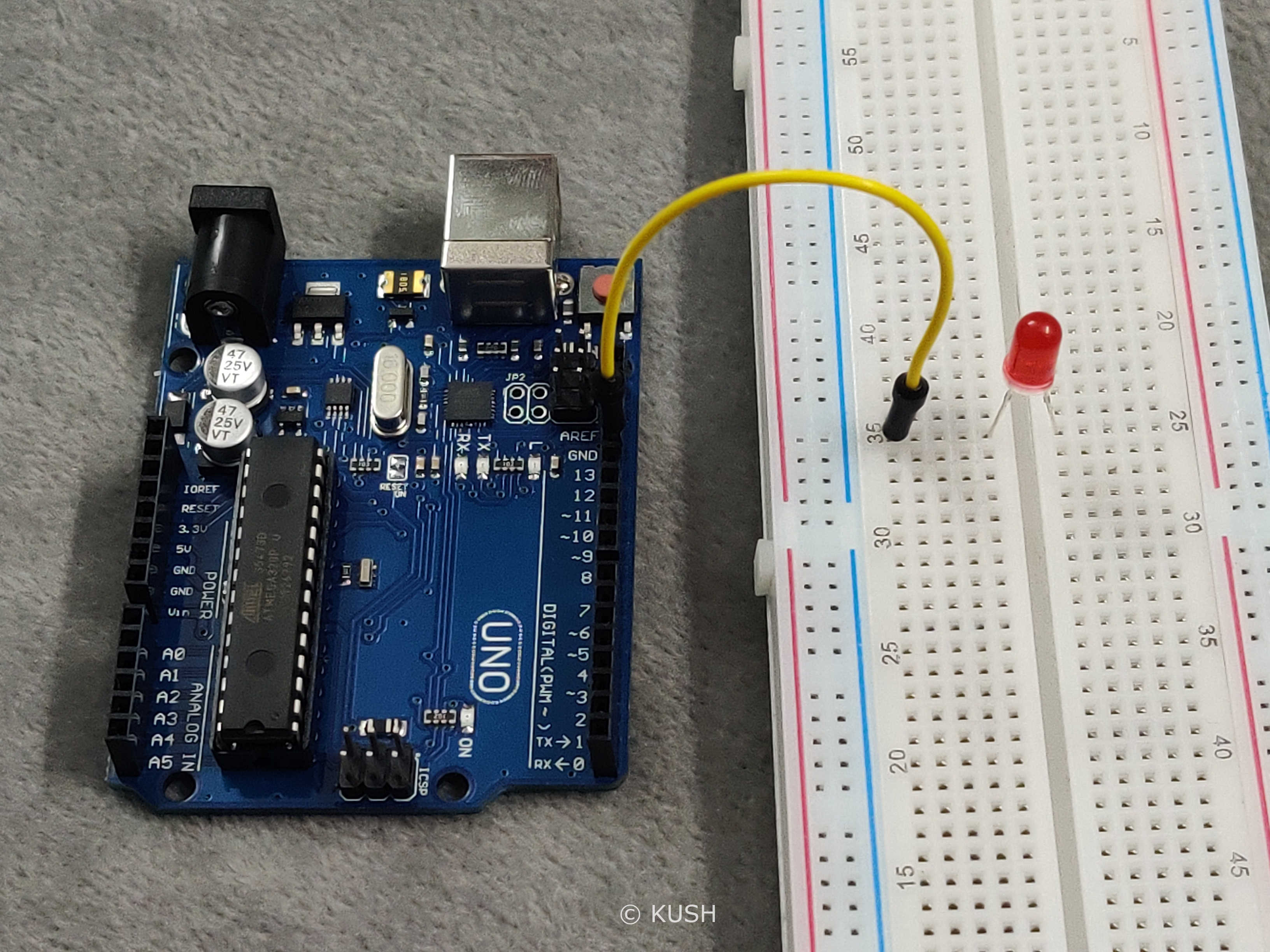
- Now take the LED and insert the longer leg (Anode) into one of the holes to which the jumper wire is connected and insert the other leg (Cathode) to any other group of holes
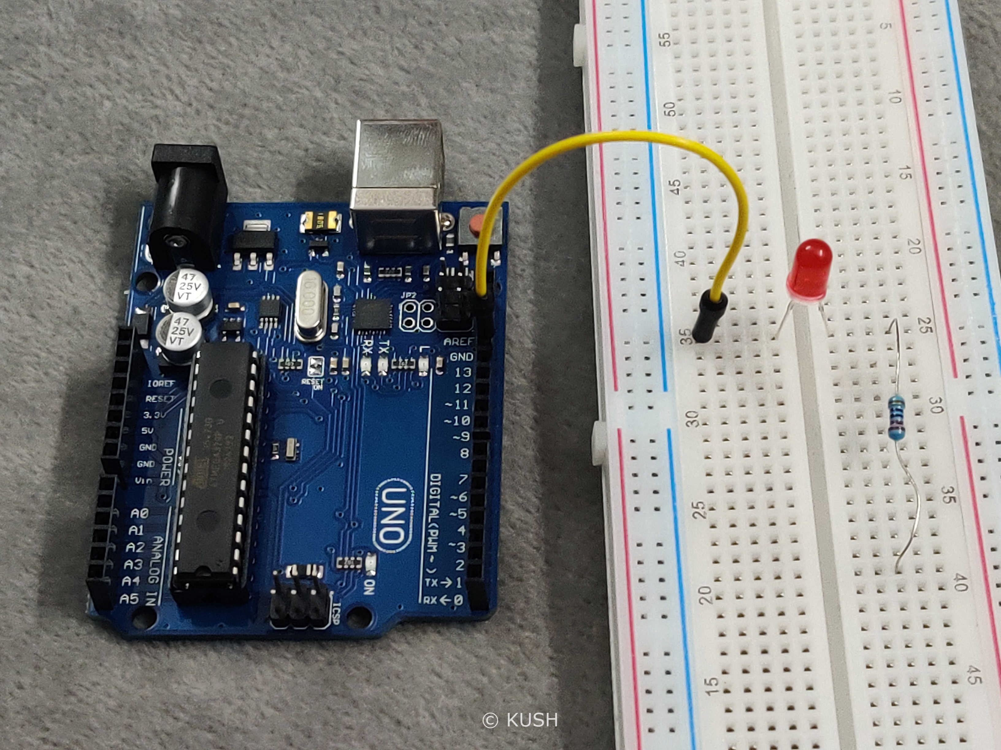
- Now take the resistor and connect it’s one side to the shorter (cathode) leg of the LED and another side to any other group of holes
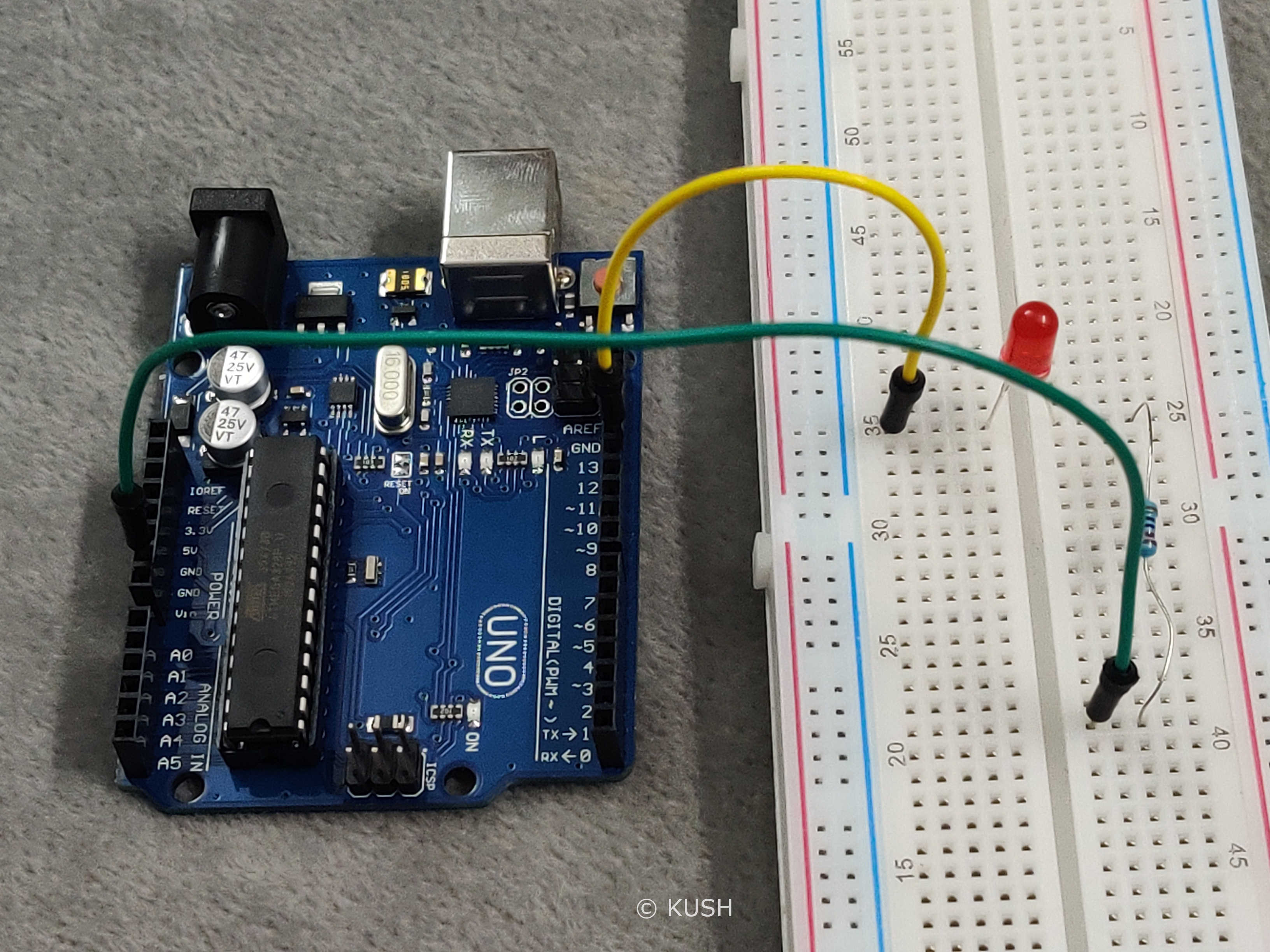
- Now take another jumper wire and connect one end to the ground pin on the Arduino and connect the other end of the jumper wire to that side of the resistor, to which LED is not connected.
Hardware Explanation:
As the LED and the Jumper wire are in the same group of holes, therefore the LED will get connected to the pin13 on the Arduino. And as the cathode leg of the LED and the resistor are in the same of group of holes, they get connected. The other side of the resistor is grounded, therefore the LED gets protected from fusing at the time of excess current.
As the assembly of hardware is done, now it’s time for writing the program and uploading it to the Arduino.
Note: For programming the Arduino, C/C++ language is used. If you don’t know anything about C, just make sure to pay more attention to it. I’ve explained the code and also added comments within the program for better understanding.
Program:
int LEDpin = 13;
void setup (){
  pinMode(LEDpin, OUTPUT);
}

void loop()
{
  digitalWrite(LEDpin, HIGH);
  delay(1000);
  digitalWrite(LEDpin, LOW);
  delay(1000);
}
For reference go to Arduino IDE: file > examples > basics > blink
Program Explanation:
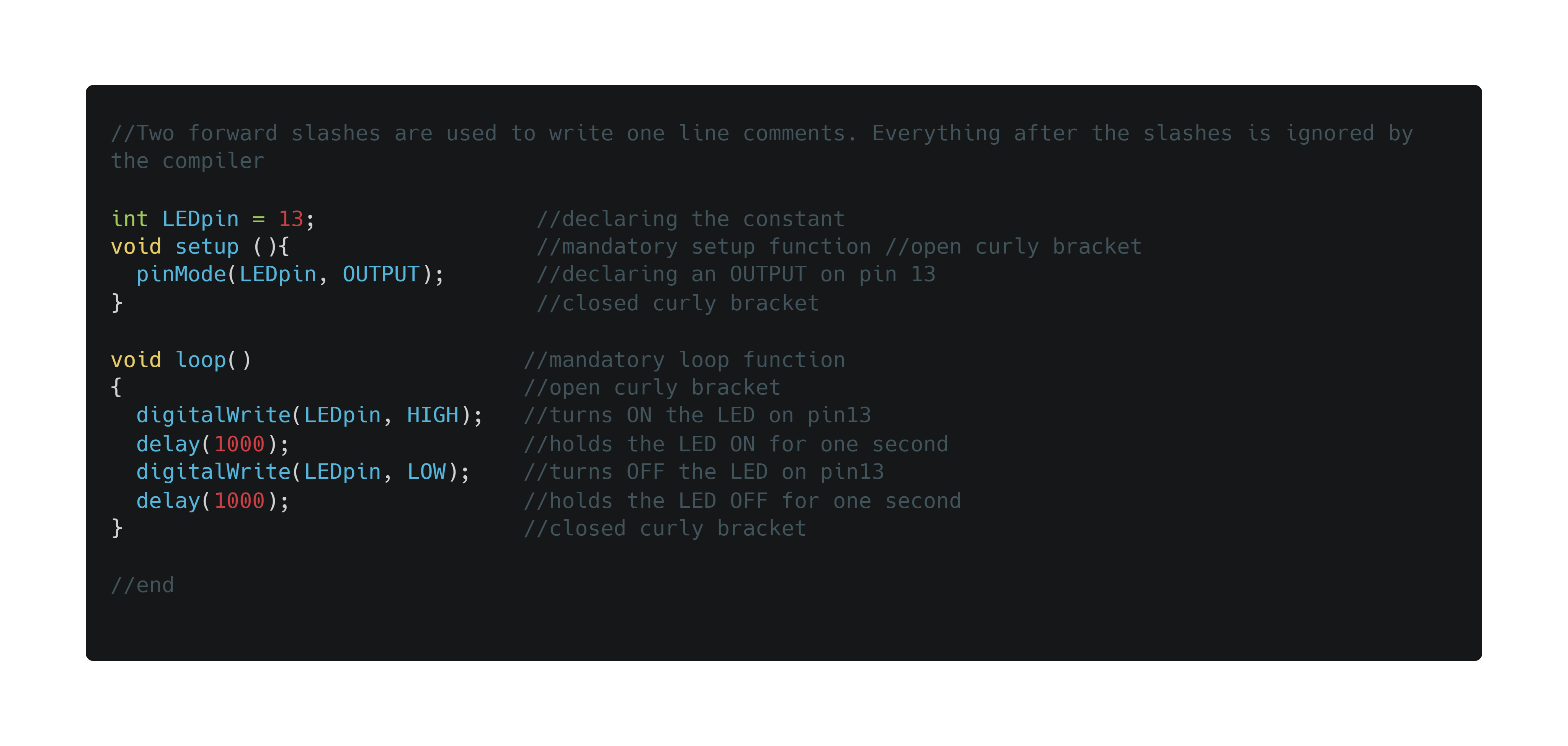
In C language, the first step is to declare the constant. Here, by using ‘int LEDpin = 13’ we declare that “LEDpin” is a constant, having an ‘integral’ value 13, which is actually our desired PIN on the Arduino. Now, in Arduino sketch the “void setup” and “void loop” are the two main functions which are mandatory for every Arduino sketch. The ‘Setup’ function is only executed once at the beginning of the program and the ‘loop’ function executes repeatedly. The term ‘void’ here is used to signify that these functions do not return anything and they don’t take any arguments (Note: Argument is as a value provided to the function whenever we call it).
The function ‘pinMode’ is used to declare an INPUT or OUTPUT, which in our case is the OUTPUT at digital pin 13. Now in order to make the LED blink we will use the function ‘digitalWrite’ which basically writes the passed argument to the specified digital pin. Therefore the statement ‘digitalWrite(LEDpin, HIGH);’ makes the LED on pin13 ‘HIGH’ i.e. turn ON. The curly brackets ‘{}’ after any statment is used to define a clear scope and is also used to group statements for better understanding. (Note: an open curly bracket must always be closed after grouping the statements)
Now the function ‘delay’ takes one argument in milliseconds which holds the LED on that state for the specified time. Therefore, the statement ‘delay(1000);’ makes the LED glow and hold it for one second. The statment ‘digitalWrite(LEDpin,LOW);’ does exact same thing as ‘digitalWrite(LEDpin, HIGH);’ but instead of turning the LED ‘ON’, it makes the LED on pin13 ‘LOW’ i.e. turn OFF and ‘delay(1000);’ turns ‘OFF’ the LED and holds it for a second.
You might be wondering that what is the use of a semicolon ‘;’ after every piece of code. Well, in C/C++ semicolon acts as a Terminator and it used to tell the compiler that we have reached the end of the command. Semicolon at the end of a command is mandatory in C/C++ language.
Now we are done with our Program and Hardware. It’s time to upload the sketch to the Arduino.
- Use the USB cable provided with Arduino to connect it with the PC.
- Use ‘Upload’ to verify and upload the sketch to the Arduino.
Note: If you get any errors while compiling the sketch, just make sure the Arduino is connected correctly to the PC and the ‘board’ & ‘port’ is specified in the tools menu. Also check for any errors in the code itself, especially look for unclosed curly brackets or missing semicolons at the end of the statements.
Once the program is successfully verified and uploaded to the Arduino we will see a ‘Done Uploading’ message at the bottom of the screen and the built-in and external LED connected to the Arduino starts blinking.
We can also change the pattern of the blinking LED just by playing around with ‘delay’ and by adding different ‘digitalWrite’ functions.
For ex.
int LEDpin = 13;
void setup (){
  pinMode(LEDpin, OUTPUT);
}

void loop()
{
  digitalWrite(LEDpin, HIGH);
  delay(2000);
  digitalWrite(LEDpin, LOW);
  delay(500);
  digitalWrite(LEDpin, HIGH);
  delay(500);
  digitalWrite(LEDpin, LOW);
  delay(500);
  digitalWrite(LEDpin, HIGH);
  delay(3000);
  digitalWrite(LEDpin, LOW);
  delay(500);
}

//end
Click Here to see the result of the above code
As you can see, now the pattern of blinking LED has been changed.
Conclusion:
In this blog we looked at some C language functions and their uses. We also looked at a basic layout of Arduino sketch and also learnt how to make an external LED blink with different patterns. This was just a basic Example; We will keep stepping up. So for many more such projects, stay tuned!
Thank You!
Share on: